My goal was to study the double pass reflection in the human eye and how objective measurements that rely on this double pass are affected. In particular, I studied how monochromatic aberrations in the eye change the light patterns (or reflex) observed in the pupil with eccentric photorefraction. Eccentric photorefraction is a technique used to estimate the refractive state of the eye. The following illustration shows a typical eccentric photorefractor and the expected the reflex in the pupil for different refractive states.
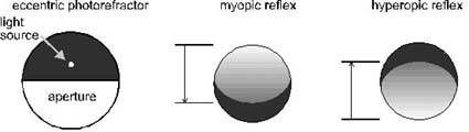
a) Crescent extent measurements
b) Slope-based photorefraction
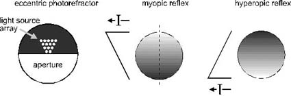
Figure 1: Typical crescents observed in eccentric photorefraction.
The light source and aperture on the left side of (a) and (b) can be fit
onto the front of any imaging camera. (a) The crescent extent technique
often uses an eccentric photorefractor with a single small source at a
relatively large eccentricity from the aperture. The right figures
show the reflex or crescent that appears in the pupil. The arrows to the
left of each pupil image mark the limits of the crescent. The extent
of the crescent along the pupil meridian is used to deduce the refractive
state. Larger crescents sizes indicate the eye has a greater defocus
with respect to the camera position. If the eye is focused in front
of the photorefractor, the crescent appears on the same side of the eye
as the light source. The opposite occurs for eyes that are hyperopic
with respect to the photorefractor. When the eye is focused on or
near the camera, no crescent is observed. The region in which no
crescent is observed is called the dead zone (Bobier and Braddick, 1985).
(b) A photorefractor configuration based on a design by Schaeffel
et al. (1987) is shown. The right figures show the intensity distribution
or reflex that appears in the pupil. The reflex fills the pupil and the
slope of the intensity profile is used to deduce the refractive state.
The line to the left of each pupil shows the intensity profile across the
vertical meridian of the pupil (shown by the dashed line). As the refractive
state increases in either direction, the slope of the intensity profile
increases.
The advantage of eccentric photorefraction is that it is quick and remote making it useful for measuring refraction in children. It has also been used to measure refraction in many animal species for which all other techniques are impractical (Schaeffel et al., 1994)
Aberrations in the eye have profound effects on the light reflex that appears in the pupil. In an experiment, I induced three different aberrated wavefronts in a single eye through the use of varifocal contact lenses. I found that even though the eye was focused on the eccentric photorefractor, the reflexes in the pupil appeared vastly different. The following figure shows the reflexes obtained under three three aberration conditions.

Figure 2: Pupil reflexes for three aberration conditions
in the same eye using a laterally displaced point source at 1 mm eccentricity
and a 0.33 m camera-to-eye distance. The bright spot in the center of each
image is a reflection from the cornea and can be ignored. In each case
the eye is focused on the camera. For the unaided eye, the aberrations
are low so the reflex is flat and dim as expected for an eye focused on
the camera. For the PA1 lens, the aberration is a combination of positive
spherical aberration and coma. For the PS45 lens the aberration is mainly
negative spherical aberration. The different aberrations cause vastly different
reflexes in the pupil.
I developed a geometrical model with which the intensity variations across these reflexes can be estimated for any aberration (Roorda et al, 1995). The model showed that aberrations account for most of the irregularity in the eccentric photorefraction reflexes in the human eye and can result in severe misdiagnoses of refractive state. On the bright side, I showed that slope-based photorefractors, such as the one shown in figure 1(b) are least affected by aberrations (Roorda et al, 1997). I showed that as the size of the light source is increased, the intensity profiles become more linear and the slope of the reflex changes linearly with refractive state, even when aberrations are present. The change in reflex slope as a function of refractive state for two different light source configurations are shown in figure 3
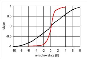
Figure 3: Change in reflex slope as a function of refractive
state for a point light source at 2 mm (red line) and an extended light
source from 0 to 30 mm eccentricity. In both cases the eye has 1.83 D of
positive spherical aberration and the distance from the eye to the camera
is 1 m. Normally, one expects the slope to be zero at the camera position
(-1 D) but the point where the best-fit slope is zero occurs for a more
hyperopic state (to compensate for the positive aberration). The use of
an extended source increases the range where there is a continuous change
in slope with refractive state almost 10 fold over the use of a point source.
Useful Eccentric Photorefraction Refererences
Berny, F. & Slansky, S. (1969) Wavefront Determination
resulting from Foucault Test applied to the Human Eye and Visual Instruments.
In: Home Dickon, J. (Ed) Optical Instruments and Techniques, (pp. 375-385).
London: Oriel Press.
Bobier, W.R. & Braddick, O.J. (1985) Eccentric photorefraction:
Optical analysis and empirical measures. Am. J. Optom. Physiol. Opt. 62,
614-620.
Campbell, M.C.W., Bobier, W.R. & Roorda, A. (1995)
Effect of monochromatic aberrations on photorefractive patterns. J. Opt.
Soc. Am. A 12, 1637-1646.
Howland, H.C. (1985) Optics of photoretinoscopy: Results
from ray tracing. Am. J. Optom. Physiol. Opt. 62, 621-625.
Kaakinen, K. (1979) A simple method for screening of
children with strabismus, anisometropia or ametropia by simultaneous photography
of the corneal and fundus reflexes. Acta Ophthalmologica 57, 161-171.
Roorda, A., Campbell, M.C.W. & Bobier, W.R. (1995)
Geometrical theory to predict eccentric photorefraction intensity profiles
in the human eye. J. Opt. Soc. Am. A 12, 1647-1656.
Roorda, A., Campbell, M.C.W. & Bobier, W.R. (1997)
Slope-based eccentric photrefraction: theoretical analysis of different
light source configurations and effects of ocular aberrations. J. Opt.
Soc. Am. A 14, 2547-2556.
Rosengren, B. (1937) A method of skiascopy with the electric
ophthalmoscope. Acta Ophthalmologica 15, 501-511.
Schaeffel, F., Farkas, L. & Howland, H.C. (1987)
Infrared photoretinoscope. Appl. Opt. 26, 1505-1509.
Schaeffel, F., Hagel, G., Eikermann, J. & Collett,
T. (1994) Lower field myopia and astigmatism in amphibians and chickens.
J. Opt. Soc. Am. A 11, 487-495.
Schaeffel, F., Wilhelm, H. & Zrenner, E. (1993) Inter-individual
variability in the dynamics of natural accommodation in humans: Relation
to age and refractive errors. J. Physiol. 461, 301-320.
Uozato, H., Saishin, M. & Fukuma, Y. (1992) The photorefractor
PR-1000 for refractive screening of infants. In: Shimizu, K. (Ed) Current
Aspects in Ophthalmology, Volume 1, (pp. 704-708). London: Exerpta Medica.